

Fastener Parameters
Material & Joint Control
2D CAD Assembly Blueprint
Key Results
VDI 2230 Curve & Friction
Point: 293.5 N·m @ 101.6 kN300 × 600 / Sticky
Tool Overview: What It Does & Engineering Purpose
The Bolt Torque & Preload Calculator is an authoritative client-side engineering engine designed to determine the precise tightening torque (TA), clamp load preload (FM), tensile stress area (As), and combined von Mises tightening stress (σeq) for metric (ISO/DIN) and imperial (UNC/UNF) threaded fasteners.
Critical Fundamentals of Threaded Fastener Clamping
A threaded fastener functions as a high-stiffness tension spring. Your wrench does not “lock” the joint—it elastically elongates the fastener shank to store thousands of Newtons of clamping tension.
- The 90/10 Friction Reality (~10% / 90%): Only 10% to 15% of applied torque generates useful axial clamp tension (TP). The remaining 85% to 90% is consumed overcoming friction under the bolt head or nut collar (50%) and along the 60° thread flanks (40%).
- Target Yield Utilization (ν = 75% – 90%): VDI 2230 recommends targeting 75% to 90% of bolt proof/yield strength (Rp0.2). Under-tightening causes joint separation and rapid fatigue failure, while over-tightening risks permanent plastic necking and thread stripping.
- Friction Sensitivity (> 25% Clamping Swing): Thread and bearing friction coefficients (μ) are highly sensitive to surface plating and lubrication. A ±0.02 shift in μ alters developed clamping force by over 25% at identical torque wrench settings.
Dual Calculation Solvers: This tool provides both the standard empirical Nut Factor Model (T = K · D · F) for quick field estimation and the complete VDI 2230 / Kellermann-Klein 3-Way Torque Partitioning for critical structural, aerospace, and pressure boundary joints.
Step-by-Step Guide: How to Use the Calculator
Follow this 5-step engineering workflow to configure your fastener assembly, inspect live CAD blueprint geometry, and extract certified tightening parameters:
Step 1: Select Thread Standard, Nominal Diameter & Pitch
Choose between Metric (ISO 261 / DIN 13) or Imperial (Unified Inch UNC/UNF). Select the nominal major diameter (d) and thread pitch (P). The engine instantly calculates nominal tensile stress area (As) and pitch diameter (d2).

Step 2: Set Material Strength Class & Target Yield Utilization
Pick the fastener strength grade (e.g., ISO Class 8.8, 10.9, 12.9; SAE Grade 5, 8; or Stainless A2-70/A4-80). Adjust the target yield utilization slider (η). For general structural joints, 75–85% is standard; for high-performance automotive/aerospace, 90% is typical.

Step 3: Define Friction Conditions & Advanced Joint Controls
Select clamped workpiece materials and lubrication presets (Dry, Lightly Oiled, Zinc Plated, Anti-Seize). Configure washer standards (ISO 7089 Flat) and nut protrusion to account for thermal gradients and embedment losses.

Step 4: Inspect Parametric 2D CAD Assembly Blueprint
Verify clamped plate thicknesses (T1, T2), solid shank engagement (ls), and thread clearance. Use the interactive toolbar to toggle FEA Stress rainbow distributions, Vectors, or test tightening animations in real time.

Step 5: Extract Tightening Torque, Preload & Safety Checks
Read the required tightening torque in N·m, ft·lb, and in·lb alongside target clamping force in kN and lbf. Verify that bearing contact stress remains safely below workpiece yield and check the VDI 2230 elastic tightening curve.

Significance of Each Option & Parameter in Detail
Precision joint design requires an understanding of how each geometric, metallurgical, and tribological input influences clamp load reliability.
1. Fastener Geometry & Stress Area Parameters
Threaded fasteners carry tension across an irregular helical profile. The calculation of load capacity relies on specific reference diameters defined by ISO 724 and ASME B1.1:
| Parameter | Symbol | Formula / Standard | Physical & Engineering Significance |
|---|---|---|---|
| Nominal Major Diameter | d | ISO 724 / ASME B1.1 | Crest-to-crest outer diameter. Dictates nominal fastener size, wrench tooling, and clearance hole sizing. |
| Thread Pitch / TPI | P / TPI | P = 1 / TPI | Axial travel per 360° revolution. Coarse threads resist stripping; fine threads provide higher tensile area and superior resistance to self-loosening. |
| Tensile Stress Area | As | π/4 · (d − 0.9382 · P)2 | The effective cross-sectional area carrying axial tension. Used universally for yield load and proof load computations. |
| Pitch Diameter | d2 | d − 0.6495 · P | The theoretical cylinder where thread tooth thickness equals groove width. Governs thread flank friction torque (Tth). |
| Minor (Core) Diameter | d3 | d − 1.2269 · P | Thread root diameter. Dictates torsional shear stress capacity and resistance to combined tightening shear overload. |
Figure 1: Threaded Fastener Anatomy, Solid Shank Grip & Stress Area (As)
Annotated blueprint-style engineering diagram of a metric hex bolt: nominal major diameter (d), pitch diameter (d2), minor core diameter (d3), solid shank grip length (ls), threaded length (b), thread pitch (P), and the critical tensile stress area (As) calculated between d2 and d3 per ISO 898-1 and VDI 2230.

2. Fastener Material Strength Classes & Property Matrix
Fastener grades define tensile yield strength (Rp0.2), nominal ultimate strength (Rm), and non-destructive proof stress (Sp). Compare the primary global strength classes:
| Standard & Class | Type | Tensile Rm (MPa / ksi) | Yield Rp0.2 (MPa / ksi) | Proof Stress Sp (MPa / ksi) | Hardness | Common Applications |
|---|---|---|---|---|---|---|
| ISO Class 4.6 | Metric | 400 MPa (58 ksi) | 240 MPa (35 ksi) | 225 MPa (33 ksi) | 114–209 HB | Light sheet metal, non-structural covers. |
| ISO Class 8.8 | Metric | 800 MPa (116 ksi) | 640 MPa (93 ksi) | 580 MPa (84 ksi) | 22–32 HRC | Standard industrial machinery, structural steel framing. |
| ISO Class 10.9 | Metric | 1000 MPa (145 ksi) | 940 MPa (136 ksi) | 830 MPa (120 ksi) | 32–39 HRC | Automotive chassis, heavy equipment, pressure flanges. |
| ISO Class 12.9 | Metric | 1200 MPa (174 ksi) | 1080 MPa (157 ksi) | 970 MPa (141 ksi) | 39–44 HRC | High-stress tooling, engine cylinder heads, precision fixtures. |
| SAE Grade 5 | Imperial | 120 ksi (827 MPa) | 92 ksi (634 MPa) | 85 ksi (586 MPa) | 25–34 HRC | General automotive & industrial mechanical assemblies. |
| SAE Grade 8 | Imperial | 150 ksi (1034 MPa) | 130 ksi (896 MPa) | 120 ksi (827 MPa) | 33–39 HRC | Heavy truck suspension, aerospace ground equipment. |
| ASTM A193 B7 | Imperial | 125 ksi (860 MPa) | 105 ksi (724 MPa) | 95 ksi (655 MPa) | ≤ 35 HRC | High-temperature pressure piping, ASME boiler flanges. |
| A2-70 / A4-70 (304/316) | Stainless | 700 MPa (101 ksi) | 450 MPa (65 ksi) | 450 MPa (65 ksi) | 160–220 HB | Marine, food processing, chemical processing (Anti-seize mandatory). |
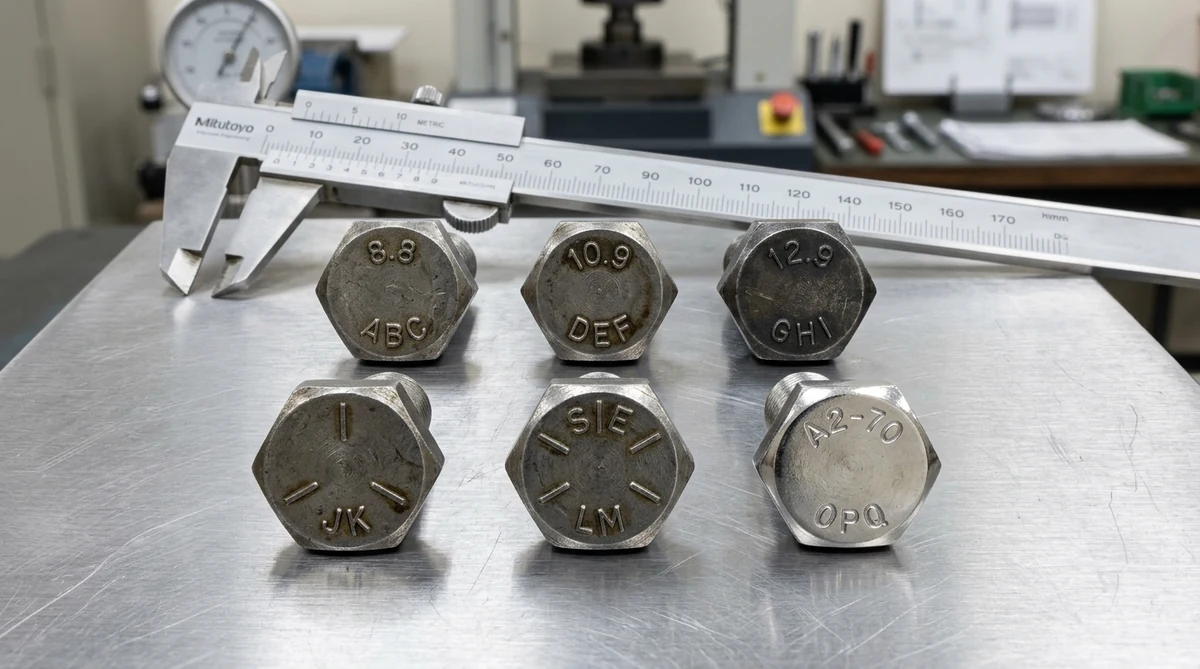
Figure 2: Bolt Head Markings & Property Class Identification
Macro laboratory photograph of forged steel hex bolt heads on an inspection surface plate. Top row displays Metric Property Classes: Class 8.8 (800 MPa tensile / 640 MPa yield), Class 10.9 (1040 MPa tensile / 940 MPa yield), and Class 12.9 (1220 MPa tensile / 1100 MPa yield). Bottom row displays Imperial SAE Grades: Grade 5 (3 radial slashes), Grade 8 (6 radial slashes), and A2-70 austenitic stainless steel.
3. Friction Coefficients (μ) & Nut Factor (K) Matrix
Friction is the single largest variable in torque-tension engineering. Lubricants and surface platings dramatically modify the effective Nut Factor (K):
| Surface Finish & Lubrication State | Thread Friction (μth) | Bearing Friction (μb) | Nut Factor (K Range) | Preload Scatter (±%) | Engineering Recommendation |
|---|---|---|---|---|---|
| Dry Plain Steel (Degreased / As-Received) | 0.18 – 0.25 | 0.18 – 0.25 | 0.20 – 0.24 | ± 30% | Avoid in critical joints due to high friction scatter and galling risk. |
| Light Machine Oil (Clean Black Oxide / Steel) | 0.12 – 0.15 | 0.12 – 0.15 | 0.15 – 0.17 | ± 20% | Standard shop baseline for general machine building and assembly. |
| Zinc Electroplated (Dry / Unwaxed) | 0.17 – 0.22 | 0.17 – 0.22 | 0.19 – 0.22 | ± 25% | Zinc-on-zinc contact causes micro-sticking. Consider waxed hardware. |
| Anti-Seize Paste (Nickel / Copper / Moly) | 0.08 – 0.12 | 0.08 – 0.12 | 0.10 – 0.12 | ± 15% | Mandatory for stainless steel 304/316 and high-temperature studs. |
| PTFE / Xylan Fluoropolymer Coating | 0.06 – 0.09 | 0.06 – 0.09 | 0.08 – 0.10 | ± 10% | Subsea flanges, offshore marine, and chemical process piping. |
4. Joint Clamping Stackup & Thread Engagement
Proper joint compliance requires adequate clamping grip length (LK) and thread engagement (Le):
- Grip Length Rule (LK ≥ 4 · d): Maintaining a clamp length at least 4 times fastener diameter provides sufficient elastic bolt stretch (δB) to absorb thermal differential expansion and resist vibration loosening.
- Solid Shank Shear Plane: Ensure the unthreaded solid shank (ls) spans across the joint shear seam rather than the weaker threaded section.
- Tapped Hole Minimum Engagement (Le): When bolting into tapped blind holes, ensure Le ≥ 1.0 · d in steel and Le ≥ 1.8 – 2.2 · d in aluminum or cast iron to prevent internal thread stripping before bolt fracture.
Figure 3: Industrial Bolted Flange Joint Stackup & Grip Compliance
Real-world high-pressure pipe flange bolted assembly featuring ASTM A193 Grade B7 studs and Grade 2H heavy hex nuts. The assembly highlights hardened flat washers (ASTM F436) seated under each nut to prevent embedment into softer flange steel, maintaining an elastic grip length ratio (LK ≥ 4d) and ensuring 2 to 3 thread pitches extend cleanly past the nut face.

Advanced Mechanics: VDI 2230 & Kellermann-Klein Derivation
In standard engineering practice (VDI 2230 / Kellermann-Klein), tightening torque is divided into three distinct parts:
1. The 3-Part Torque Breakdown (Where Does Your Torque Go?)
When torque is applied to a bolt, only about 10% to 15% actually stretches the fastener. The remaining 85% to 90% is consumed overcoming friction:
Ttotal = TPitch (Bolt Stretch) + TThread (Thread Friction) + TBearing (Collar Friction)
| Torque Part | Formula | Share (%) | What It Does |
|---|---|---|---|
| 1. Pitch Torque (TP) | FM · P / (2π) | 10% – 15% | Useful work: stretches the bolt to generate clamping preload. |
| 2. Thread Friction (Tth) | FM · μth · d2 / (2 · cos 30°) | 35% – 45% | Overcomes friction between male and female mating thread flanks. |
| 3. Bearing Friction (Tb) | FM · μb · Dkm / 2 | 45% – 55% | Overcomes friction under the rotating bolt head or nut face. |
Figure 4: The 90/10 Torque-Tension Partitioning Model
Cutaway cross-sectional mechanics of a tightened bolted joint illustrating the 3 distinct torque sinks: 50% Underhead Bearing Friction (Tb) lost under the rotating collar, 40% Thread Flank Friction (Tth) dissipated between male and female mating helical surfaces, and only 10% to 15% Useful Clamp Force (TP) converted into elastic bolt tension.

2. Simplified Shop Formula: The Nut Factor (K)
For quick shop calculations, the 3-part formula simplifies to the standard equation:
T = K · d · FM
- K ≈ 0.20: Standard dry, unlubricated steel bolts.
- K ≈ 0.15: Lightly oiled or zinc-plated fasteners.
- K ≈ 0.10 – 0.12: Fasteners with anti-seize paste or moly lubricant.
3. Combined von Mises Tightening Stress (σeq)
During tightening, the bolt experiences both axial tension (from stretching) and torsional shear (from thread friction). This combined loading creates an equivalent stress (σeq) that is 10% to 15% higher than pure tension:
σeq = √( σtension² + 3 · τtorsion² ) ≤ Rp0.2
To prevent permanent fastener yield or necking, always verify that σeq does not exceed the bolt yield strength (Rp0.2).
Step-by-Step Worked Engineering Example
Let us calculate the exact tightening torque, preload, and von Mises stress for an M16 × 2.0 Class 10.9 structural flange bolt clamped with lightly oiled hardware:
Problem Statement: M16 × 2.0 Class 10.9 Fastener Sizing
- Given Inputs: Metric M16 Coarse (d = 16.0 mm, P = 2.0 mm), ISO Class 10.9 (Rp0.2 = 940 MPa, Sp = 830 MPa), Target Utilization ν = 0.85 (85%), Light Machine Oil (μth = 0.13, μb = 0.14), Underhead Bearing Dkm = 19.85 mm.
-
Calculate Tensile Stress Area (As):
As = (π / 4) · [16.0 − (0.938194 · 2.0)]² = (π / 4) · (14.1236)² = 156.67 mm² ≈ 157 mm² -
Calculate Preload at 85% Yield (FM):
F0.2 = 156.67 mm² × 940 N/mm² = 147,270 N = 147.27 kN
FM = 0.85 × 147.27 kN = 125.18 kN (28,140 lbf) -
Compute 3 Torque Components (VDI 2230):
• Useful Pitch Torque:TP = 125,180 · (2.0 / 2π) / 1000 = 39.85 N·m (13.0%)
• Thread Flank Torque:Tth = 125,180 · [ (0.13 · 14.701) / (2 · 0.866) ] / 1000 = 138.07 N·m (45.1%)
• Underhead Bearing Torque:Tb = 125,180 · [ (0.14 · 19.85) / 2 ] / 1000 = 128.02 N·m (41.9%) -
Calculate Total Required Tightening Torque:
Ttotal = 39.85 + 138.07 + 128.02 = 305.94 N·m ≈ 306 N·m (225.7 ft·lb)
Effective Nut Factor:K = 305.94 / (0.016 × 125,180) = 0.153 -
Verify von Mises Tightening Stress:
σtensile = 125,180 / 156.67 = 798.99 MPa
τtorsion = 16 · (39.85 + 138.07) × 1000 / (π · 13.546³) = 114.72 MPa
σeq = √[ (798.99)² + 3 · (114.72)² ] = 823.32 MPa ≤ 940 MPa (√ Passed – 87.6% utilization)
Bolted Joint Failure Modes & Shop Risk Mitigation
Over 85% of bolted joint service failures occur due to dynamic relaxation, vibration loosening, or thread galling rather than simple tensile overload.
1. Embedment Relaxation (Settling Loss fz · DIN 25201 / VDI 2230)
Under high clamping pressure, microscopic surface roughness peaks (asperities) plastically deform and flatten over the first 48 hours post-tightening. In joints with multiple clamped interfaces or painted surfaces, embedment causes an initial 2% to 8% drop in clamp load. Compensate by tightening 5% above nominal or performing a 24-hour retorque audit.
2. Transverse Dynamic Loosening & Junker Fatigue (Junker Test Standard)
Transverse (shear) cyclic vibration causes relative micro-slip across thread flanks. Once friction is momentarily cancelled, the internal helix lead angle drives the fastener to unthread spontaneously. Standard split-ring lock washers are largely ineffective under severe vibration. Use wedge-locking washers (Nord-Lock), prevailing-torque locknuts, or anaerobic threadlockers (Loctite 243/271).
Figure 5: Bolt Fatigue Fracture Beach Marks & Thread Root Initiation
Real-world laboratory failure analysis photograph of a structural steel bolt that fractured under dynamic cyclic loading. Panel (a) shows the threaded cylindrical shank with the fracture surface exposed, clearly revealing the concentric elliptical beach marks (fatigue crack propagation) and the final rapid fracture overload zone (10 mm scale). Panel (b) shows a high-magnification stereomicroscopic view of the fatigue crack initiation site right in the thread root notch radius (2 mm scale).

3. Stainless Steel & Titanium Thread Galling (Cold Welding · ISO 3506-1)
Austenitic stainless steels (304 / 316 / A2 / A4) and titanium rely on thin passive oxide films. Under high tightening contact pressures and high rotational speed, the oxide film shears away, causing metal-to-metal micro-welding and permanent thread seizure. Mitigation: Always apply anti-seize paste (nickel or copper base), use rolled threads rather than cut threads, and run torque wrenches below 30 RPM.
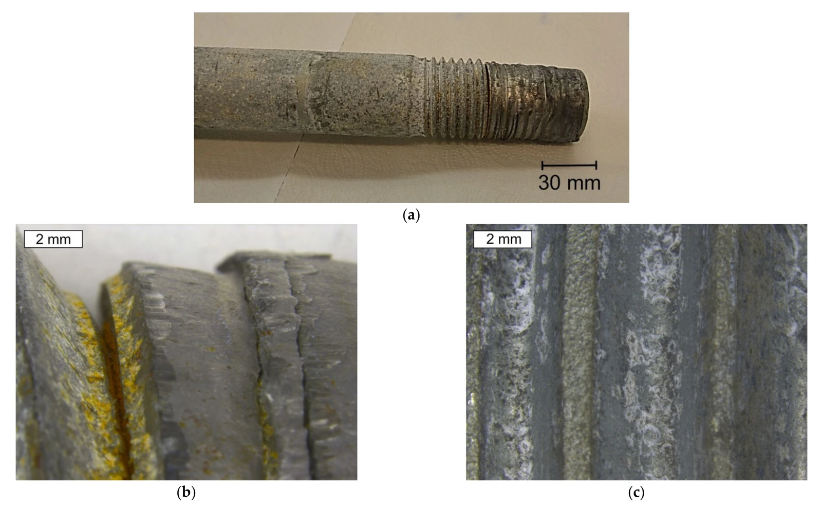
Figure 6: Severe Thread Galling, Shearing & Adhesive Cold Welding
Real-world forensic engineering macro photograph of severe thread galling and adhesive cold welding on a structural threaded fastener. Panel (a) demonstrates the macroscopic seizure zone where galling stripped and sheared the helical threads under high contact torque (30 mm scale). Panels (b) and (c) provide stereomicroscopic magnifications (2 mm scale) revealing root micro-cracking and torn metallic asperities transferred across helical flanks.
Tightening Tools & ASME PCC-1 Tightening Factor (αA)
The accuracy of bolt preload depends directly on the tightening method used. The ASME PCC-1 Tightening Factor (αA = FM,max / FM,min) defines preload scatter:
| Tightening Method | Tightening Factor (αA) | Preload Accuracy | Torsional Stress | Typical Industrial Usage |
|---|---|---|---|---|
| Manual Hand Wrench / Impact Gun | 1.70 – 2.00 | ± 35% – 50% | High | Non-critical framing, light structural assembly. |
| Calibrated Clicker Torque Wrench | 1.40 – 1.60 | ± 20% – 30% | High | Standard machine building, automotive repair, plant maintenance. |
| Torque + Angle (Turn-of-Nut per EN 14399) | 1.10 – 1.20 | ± 8% – 10% | Moderate | Engine cylinder heads, structural bridge girders, crane booms. |
| Hydraulic Bolt Tensioner | 1.15 – 1.25 | ± 10% – 12% | Zero (τ = 0) | Wind turbine hubs, subsea oil & gas, nuclear pressure vessels. |
| Ultrasonic Preload Telemetry (Echo Meter) | 1.05 – 1.08 | ± 3% – 5% | Monitored | Aerospace rocket staging, critical high-pressure steam turbines. |
Figure 7: Industrial Tightening Equipment & Scatter Factors (αA)
Comparative analysis of shop and field tightening equipment per ASME PCC-1: Panel 1 (Left) — Calibrated Micrometer Clicker Torque Wrench (αA = 1.40–1.60, ±25% preload scatter), recommended for general structural bolting; Panel 2 (Center) — Digital Electronic Torque-Angle Wrench (αA = 1.10–1.20), combining torque and rotation-angle monitoring for yield-controlled tightening; Panel 3 (Right) — Heavy-Duty Hydraulic Torque Wrench (αA = 1.15–1.25) clamped onto a bolted flange nut, used in structural steel and pressure vessel applications.

Frequently Asked Questions (FAQ)
Expert answers to critical shop, field, and mechanical design questions regarding fastener torque and clamping preload:
1. Why does only 10% to 15% of torque convert into clamping force?
Threaded fasteners are inclined planes wrapped around a cylinder. When turning a bolt, approximately 50% of your wrench torque is consumed overcoming friction under the bolt head or nut collar, and another 40% is consumed overcoming sliding friction along the 60° thread flank ramps. Only the remaining 10% to 15% performs useful work driving the fastener up the helix incline to elastically stretch the bolt shank.
2. Can high-strength bolts (Grade 8 / Class 10.9) be safely reused?
Bolts tightened purely within their elastic region (≤ 85% of yield strength) can generally be reused 2 to 3 times in non-critical machinery, provided threads are thoroughly cleaned, inspected for damage/galling, and re-lubricated. However, fasteners tightened using Torque-Angle (Turn-of-Nut / Torque-to-Yield) enter permanent plastic deformation and must NEVER be reused. In aerospace, pressure vessels (ASME PCC-1), and automotive suspension, new fasteners are mandatory upon disassembly.
3. How does adding lubricant or anti-seize change torque requirements?
Applying lubricant, anti-seize paste, or moly grease lowers the coefficient of friction from μ ≈ 0.20 (dry steel) down to μ ≈ 0.10–0.12. Because friction is reduced, applying a dry torque specification to a lubricated bolt will generate 30% to 50% higher clamping force than intended, risking bolt necking, joint crushing, or thread stripping. Always reduce your torque wrench setting when applying lubricants.
4. What is the difference between Proof Load, Yield Strength, and Tensile Strength?
Proof Load (Sp) is the maximum non-destructive tensile load a bolt can withstand without permanent plastic deformation (typically ~90% of yield). Yield Strength (Rp0.2) is the stress level where 0.2% permanent plastic strain occurs. Ultimate Tensile Strength (Rm) is the peak engineering stress before necking and complete structural fracture occurs.
5. Why is Breakaway Torque different from original tightening torque?
Breakaway torque required to restart rotation post-assembly is typically 10% to 25% different from dynamic tightening torque. This discrepancy stems from two factors: static coefficient of friction (μs) is higher than kinetic dynamic friction (μk), and surface embedment relaxation causes a 2% to 8% drop in clamp load over time.
6. When should hardened flat washers (ASTM F436 / DIN 125) be used?
Hardened washers are essential when clamping high-strength bolts (Class 10.9/12.9 or Grade 8) against softer workpiece materials (aluminum, structural steel, or cast iron). Without hardened washers, the intense underhead bearing contact pressure exceeds the joint material yield strength, causing localized surface brinelling and immediate clamp load loss.
7. How do high and low operating temperatures affect bolt preload?
Operating temperatures affect preload through two mechanisms: material modulus degradation (steel loses ~10% elastic modulus at 300°C) and differential thermal expansion (ΔLth = (αJoint − αBolt) · LK · ΔT). For example, a steel bolt clamping an aluminum engine block will experience increased preload as temperature rises because aluminum expands at twice the rate of steel (α ≈ 23 × 10-6/K vs. 12 × 10-6/K).
8. What is the difference between Torque Control and Hydraulic Bolt Tensioning?
Torque control relies on turning a nut or bolt head, which introduces large friction scatter and high torsional shear stress into the bolt shank. Hydraulic bolt tensioning uses an annular hydraulic ram to pull the bolt shank in pure axial tension (τ = 0). Once the exact tension is reached, the nut is spun down finger-tight against the flange face, and hydraulic pressure is released, eliminating all friction-induced errors.
9. How do coarse threads compare to fine threads in torque applications?
Coarse threads (UNC / ISO Coarse) have a deeper thread tooth profile, making them faster to assemble, less sensitive to minor surface nicks, and significantly more resistant to stripping in soft materials. Fine threads (UNF / ISO Fine) possess a larger nominal tensile stress area (As) for a given diameter and a shallower helix lead angle (α), providing superior resistance to transverse vibration loosening.
10. What is the star / cross torque pattern and why is it mandatory on pressure flanges?
Tightening bolts sequentially around a circular flange face pinches the gasket unevenly on one side, causing flange tilt, localized gasket crushing, and fluid leakage. ASME PCC-1 mandates a cross-pattern (star sequence) executed in multi-pass increments (Pass 1 at 30% torque, Pass 2 at 70% torque, Pass 3 at 100% torque, followed by a final clockwise cleanup pass) to compress the joint uniformly across the entire sealing perimeter.